

Digital Communications: A Discrete-Time Approach
by Michael Rice

Carrier Phase Synchronization for BPSK Using Differential Encoding
Introduction
In the previous BPSK Simulink Exercise the phase of the unmodulated carrier was assumed known. Unfortunately, this is not the case in practice. The carrier phase is unknown and must be extracted from the received signal using a carrier phase recovery subsystem. In this exercise, you will design a PLL-based carrier phase recovery subsystem for BPSK which will be used to process BPSK modulated data contained in the file bpskcrdata.matTo deal with the 180-degree phase ambiguity of the PLL-based carrier phase synchronizer, this exercise uses differential encoding. In differential encoding, the two possible phase shifts (0 and 180 degrees) are determined by the binary input instead of the absolute phase of the carrier. Detection and phase synchronization are carried out as usual. The resulting decisions, however, are for differentially encoded bits. A differential decoder must be used to recover the information bits.
Textbook References
M-ary QAM: Section 5.3, discrete-time realizations: Section 5.3.2, partial response pulse shapes: Section A.2, discrete-time PLL: Section C.2, carrier phase synchronization for BPSK: Section 7.3, differential encoding for phase ambiguity resolution, general discussion: Section 7.7.2, BPSK example: Section 7.7.2.Specifications
 |
| ||||||||||||||||||||||
| packet format |
the frame format is shown below

The frame is repeated 4 times to allow your PLL to acquire and lock. |
Design the Detector
Design the detector, shown below, using blocks from the Simulink, DSP System, and Communications System Toolboxes. I recommend you start with the detector from the BPSK Simulink Exercise and make changes as necessary.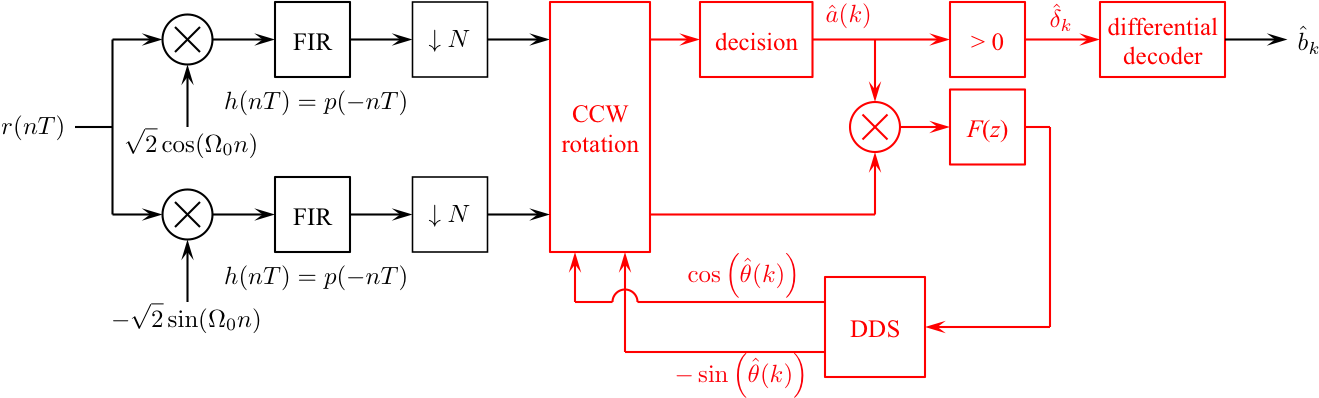
Design the loop filter to create a second order loop to the following specifications: closed-loop equivalent noise bandwidth = 0.02 (normalized to the bit rate), damping factor = 0.7071.
Exercise
- For the detector input, use the From File block and set the Filename to bpskcrdedata.mat and set the sample time to 1.
-
Set the simulation parameters as follows:
Simulation Time Start time: 0.0 Stop time: (12+(16+1582)*4)*8-1 Solver selection Type: Fixed-step Solver: discrete (no continuous states) - Run the simulation.
- The detector produces 6404 bit estimates. Even though the SYNC and DATA fields are repeated four times, the PLL does not lock until part way through the sample sequence.
- To find the data bits, look for the 16-bit SYNC pattern in the detector output. The 1582 bits following the SYNC correspond to 226 7-bit ASCII characters.
- Determine the message using either your Matlab script or an ASCII Table.
- Plot the phase error (loop filter output) and use this plot to estimate how long (measured in bits) it took your PLL to lock.
- Plot the eye diagram and signal space projections.
Brigham Young University - Provo |
Fulton College of Engineering |
The Church of Jesus Christ of Latter-day Saints
Department of Electrical and Computer Engineering, BYU, Provo, UT 84602 - (801)422-4012 - Copyright 2009. All Rights Reserved
Department of Electrical and Computer Engineering, BYU, Provo, UT 84602 - (801)422-4012 - Copyright 2009. All Rights Reserved